TECHNICAL SPECIFICATION NOTES FOR ROAD SAFETY BARRIER SYSTEMS
1. INTRODUCTION
A road safety barrier is considered to be a hazard and should only be used when the consequences of hitting it are less than the hazard/object which it is shielding. The use of a road safety barrier should only be considered as a last resort following an assessment of whether or not the mitigation of the hazard or object can be achieved through the application of the principles of clear zoning.
A clear zone is a recovery zone in which a driver may regain the control of an errant vehicle. The clear zone must be free from hazards or objects and traversable by a vehicle. Refer to SHGDM, Section 6.6: Clear Zone for more details on clear zone principles and requirements.
2. NATIONAL COOPERATIVE HIGHWAY RESEARCH PROGRAM REPORT 350 (NCHRP 350)
NCHRP 350 provides standardised procedures for the crash testing and evaluation of both permanent and temporary road safety features, including barriers, sign supports, etc.
The objective of the testing is to determine the manner in which a road safety feature performs during a vehicle crash, for typical site and traffic conditions. There are six test levels, each being defined by impact conditions, i.e. vehicle type, speed, mass, and angle of approach. A summary of the NCHRP 350 test matrix for longitudinal roadside/bridge barriers, and barrier transitions, is given in Table 1 on the next page.
NOTE: While different types of barriers have road safety features that meet a given test level, they generally have different performance characteristics.
| Test Level | Test Vehicle | Impact Speed (km/h) | Impact Angle (deg.) |
| 1 | 700/820 kg car 2000 kg Pick-up | 50 50 | 20 25 |
| 2 | 700/820 kg car 2000 kg Pick-up | 50 70 | 20 25 |
| 3 | 2000 kg Pick-up | 100 | 25 |
| 4 | 2000 kg Pick-up 8000 kg Single unit truck | 100 80 | 25 15 |
| 5 | 2000 kg Pick-up 36,000kg Semi-trailer (Van) | 100 80 | 25 15 |
| 6 | 2000 kg Pick-up 36,000 kg Semi-trailer (Tanker) | 100 80 | 25 15 |
| Table 1: NCHRP Test Matrix Summary | |||
3. SELECTION OF ROAD SAFETY BARRIER SYSTEMS
3.1 Minimum Performance Standard
The minimum performance level for a state highway road safety barrier system is NCHRP 350 Test Level 3 (TL-3). However, in many circumstances, barriers complying with higher test levels will be necessary because factors such as traffic conditions, traffic volume and composition and the cost effectiveness of various safety alternatives must all be considered in the design of road safety barrier systems.
Designers should determine the performance level required for a roadside/median barrier on a case by case basis after due consideration of all factors involved. For example:
(a) The standard roadside protection is a TL-3 barrier but some features, such as a school playground located close to the toe of fill embankment on the outside of a high speed horizontal curve, warrant the provision of a higher performance roadside barrier.
(b) High proportions of heavy and/or dangerous goods vehicles in the traffic stream will usually require TL-4 barriers as a minimum.
(c) Even higher performance barriers, ie. a TL-5 barrier that will contain 36,000 kg truck or a TL-6 barrier that will contain a 36,000 kg tanker, should be used at locations where there are high proportions of heavy
and/or dangerous goods vehicles in the traffic stream, and there would be serious consequences if such a vehicle penetrated, or rolled over, the barrier.
(d) The standard bridge edge protection is a TL-3 barrier but the Transit New Zealand Bridge Manual (Bridge Manual) edge protection criteria will often require the provision of a TL 4 barrier, which will contain an 8,000 kg truck, in most cases.
The Bridge Manual contains a method for determining the appropriate barrier test level for any given situation and it must be complied with when dealing with barriers on bridges. The method is also equally relevant for determining the appropriate test level for roadside and median barriers.
4. TYPES OF ROAD SAFETY BARRIER SYSTEMS
4.1 Roadside and Median Barriers
(a) Flexible Systems
Flexible barrier systems, e.g. wire rope barriers, are generally more forgiving than other types because most of the impact energy is dissipated by deflection of the barrier and lower impact forces are imposed on the vehicle and its occupants.
All wire rope barriers approved for use on state highways have different deflection characteristics for a given NCHRP 350 test level.
(b) Semi-rigid Systems
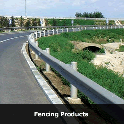
Semi-rigid barrier systems, e.g. W-Beam and Thrie-Beam barriers, are the most common type of road safety barrier used in New Zealand. This type of system redirects vehicles mainly by the beam action of the relatively strong steel rails transferring impact loads to closely spaced posts, which in turn transfer the loads to the ground.
Semi-rigid barrier systems have much less lateral deflection than flexible systems.
Examples of semi rigid road safety barrier systems available in New Zealand are:
• Strong Post W-Beam - TL-3
• Strong Post Modified Thrie-Beam - TL-4.
(c) Rigid Systems
Rigid barrier systems, e.g. concrete barriers, work by transferring vehicle impact loads directly into the ground, resisting impacts through the inertial resistance of the barrier mass and its sliding resistance across the ground. The face of these barriers is designed to absorb impact energy by partly lifting the vehicle and controlling the behaviour of the vehicle after impact.
Rigid barriers have no lateral deflection.
4.2 Bridge Barriers
Although road safety barriers on bridges tend to appear similar in design to roadside barriers they are unique in their design.
The design of bridge barriers must comply with the requirements of the Bridge Manual.
Guidelines for the retrofitting of guardrails to existing bridges are in preparation.
4.3 Crash Cushions and End Terminals
The end of a barrier is a point of major concern. A crashworthy end treatment, conforming to NCHRP 350 TL-3, must be provided when the end of a barrier is vulnerable to head-on impacts.
4.4 Transitions
A non-rigid barrier should be gradually stiffened on the approach to a connection with a more rigid object such as a bridge barrier, a retaining wall, an abutment wall, or another structural support. The transition design should result in barrier that will permit an impacting vehicle to be smoothly redirected without pocketing or snagging of the barrier.
5. TERMINALS & CRASH CUSHIONS
5.1 Terminals
The diagram below shows the three terminal behaviour types described in NCHRP 350 and how they are related to each other.
(a) Redirective Gating Terminal
Redirective gating terminals provide:
• controlled penetration of the barrier when a vehicle impacts at, or near, the nose of the device; and
• smooth redirection of a vehicle when it impacts the barrier downstream of the nose section.
Part of the length of a redirective gating terminal is usually able to be included in the length of standard barrier needed to shield a hazard, but this varies from system to system.
(b) Redirective Non-gating Terminal
Redirective non-gating terminals will smoothly redirect a vehicle, without pocketing or penetration of the barrier, when a vehicle impacts the barrier:
• at, or near, the nose of the device; or • downstream of the nose.
Most of the length of a redirective terminal will usually be able to be included in the length of standard barrier needed to shield a hazard.
(c) Non-redirective Terminal
Non-redirective terminals absorb an impacting vehicle’s kinetic energy when they are hit head-on by an errant vehicle. However, they will not control vehicles that impact at an angle and pocketing, or penetration, of the terminal may result. All non-redirective terminals are gating.
5.2 Crash Cushions
Site conditions will usually dictate the type of crash cushion needed, e.g. fixed objects such as barrier ends which are less than one metre wide should be shielded by a narrow crash cushion. Wide obstacles, e.g. those greater than 5m, are best shielded by sand barrel arrays, custom designed attenuator systems or metal-beam “bullnose” attenuators.
Kerbs and slopes can cause an impacting vehicle to become airborne and reach undesirable roll and pitch angles before impacting the crash cushion. The surface on which a crash cushion is installed should be smooth, flat, and compacted. All of the energy absorbing systems must be placed on a hard, smooth pad or surface (usually concrete) to enable the unit to be compressed uniformly during an impact. In the case of inertial crash cushions, a paved surface provides uniform support for the sand barrels and, perhaps more importantly, provides a surface on which the pattern of the array and the required masses of the modules can be permanently marked for maintenance purposes.
If a crash cushion is installed on a structure, the location of expansion joints may dictate the type of device to use, or require some modifications to the standard design, e.g. non-anchored units such as sand barrels, may be susceptible to vibration-induced movement.
Climatic conditions in a particular area should also be considered because some crash cushions are affected by above or below average temperatures and may also be more susceptible to inadvertent damage caused by operations such as snow removal.
5.3 Aesthetic and Environmental Considerations
While aesthetics are a consideration, they are not normally controlling factors in the selection of a side protection barrier, except in the environmentally sensitive locations such as recreational areas or parks. In such cases, it is important that the systems used be crashworthy as well as visually acceptable to the road controlling authority.
It is also important to consider environmental factors in the selection process.
For example:
• Barriers with considerable frontage area may contribute to a build up of drifting sand or snow in some areas.
• Metal railing barriers may deteriorate rapidly in highly corrosive urban/industrial environments.
In some cases, solid barriers may restrict sight distances of drivers entering from a side road or intersection, or may block a driver's view of a particularly scenic panorama.
6. ROADSIDE BARRIER SYSTEM MAINTENANCE
The future maintenance costs of alternate systems should be considered in the barrier selection process. Normally, the initial cost of a system increases as its strength increases, but maintenance costs decrease. Conversely, a system having a relatively low installation cost usually requires significantly more maintenance following impacts. Maintenance factors can be grouped into three categories:
6.1 Routine maintenance
Routine maintenance costs are similar for all operational roadside barrier systems. Some cleaning and painting is occasionally done, but the use of preservative-treated wood posts and galvanized steel components has nearly eliminated the need for this work. Periodic re-tensioning of cable barrier systems may be required. Graffiti on concrete barriers can present an ongoing maintenance cost. Some systems may interfere more with roadside mowing and vegetation control.
6.2 Collision maintenance
The amount and cost of repairs after an impact by a vehicle can play an important role in the system selection. The number of impacts that are likely to occur along a particular section of barrier depends on a number of factors, primarily traffic speed and volume, road alignment and the distance between the edge of the traffic lane and the face of the barrier. The extent of barrier damage for any specific impact depends upon the strength of the system.
Collision maintenance costs may become an overriding consideration in areas where traffic volumes are extremely high, and barrier impacts are frequent, such as on urban expressways and motorways where barrier repair is difficult to accomplish without interfering with road users. For this reason, rigid concrete barriers (e.g. “F-type” profile), are often preferred at such locations, particularly in median applications.
A further consideration in collision maintenance for post and rail systems is the ability of the rail element and possibly the posts to be re-used after a hit. Savings may be possible if the rail can be straightened. In some cases, of course, the rail will be damaged beyond repair, in which case the salvage/scrap value may be a consideration.
6.3 Material and Storage Requirements
Before selecting a barrier system, the future availability of the repair materials and their storage requirements should be considered. The need for stocking spare parts increases as the number of parts required increases. Thus, there are obvious advantages of using only a few barrier systems whose component parts are standardized, easy to stockpile and readily available.
7. KEY REFERENCE DOCUMENTS
| New Zealand Transport Agency | State Highway Geometric Design Manual (SHGDM) Bridge Manual |
| Joint Australian/New Zealand Standard | AS/NZS 3845: 1999 - Road Safety Barrier Systems |
| National Cooperative Highway Research Program (NCHRP) | NCHRP Report 350: Recommended Procedures for the Safety Performance Evaluation of Highway Features |
| American Association of State Highway and Transportation Officials (AASHTO) | Roadside Design Guide (AASHTO RDG) The recommended comprehensive reference for the design and installation of road safety |
| barrier systems on New Zealand state highways. |


